ESU Products |
(Click your browser's BACK button to return to the product listing)

|
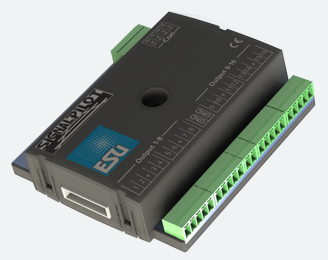
| ESU51840
SignalPilot, accessory decoder with 16 outputs Push/Pull, Removable screw terminals NOTE: For the most current instruction sheet consult the ESU website directly. The ESU SignalPilot decoder is a multi-protocol decoder designed primarily for switching daylight signals. It has 16 outputs to which micro lamps or LEDs (with series resistors) can be connected directly. Because all outputs are designed as push/pull output stages, both daylight signals with common anode as well as daylight signals with a common earth connection (common cathode) are suitable, as is the case with Viessmann® signals. Motorised semaphore signals and turnout drives can also be operated with the SignalPilot. The SignalPilot supports both DCC with RailComPlus® and Motorola®. Programming allows for each output to be assigned to any address or to a combination of addresses. The SignalPilot can be powered either directly by the digital command station or by any transformer /power supply unit providing DC or AC. The SignalPilot has 16 transistor outputs in push-pull configuration. Each output can be operated individually as continuous light, flashing light or pulse light. Here, the brightness or flashing frequency can be adjusted as well as fade-in and fade-out times. Various prototypical lighting effects such as soft dimming, fluorescent tube effect, defective fluorescent tube, gas lantern simulation, flicker light ensure a realistic result. Randomly controlled switching on/off as well as an on/off delay can also be activated. A night service extension can dim down the outputs together if so desired. The easiest method of configuring the SignalPilot is programming it with the ESU LokProgrammer. Simply choose the desired signal type, and the wiring will be displayed on the screen. The firmware of the SignalPilot can be updated with the aid of the LokProgrammer at any time. This may be necessary whenever we add new signal types. NMRA/DCC "Accessory decoder" compatible. Motorola® with up to 127 addresses. K83 compatible. Powered either by command staton or separately DC - or AC source (transformer) up to 18V AC. 16 outputs, maximum 250 mA each. Connection by means of removable terminal strips. Push/pull power amplifiers: Each output may be connected individually to either decoder ground or to the common positive return. Individual assignment of decoder addresses to the outputs (Mapping). Lighting effects and brightness can be adjusted individually. Cross-fading and time dependent sequences. Pre-programmed signal aspects. Short circuit and overload protection for all outputs. |